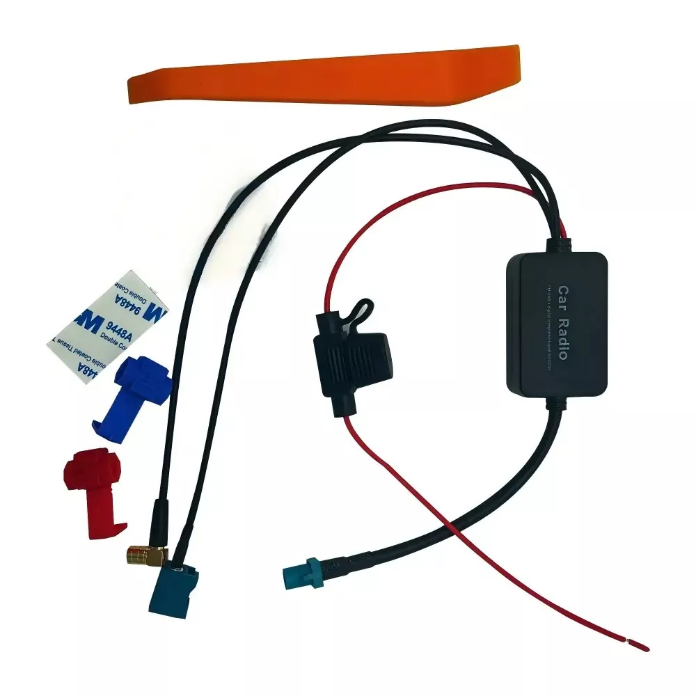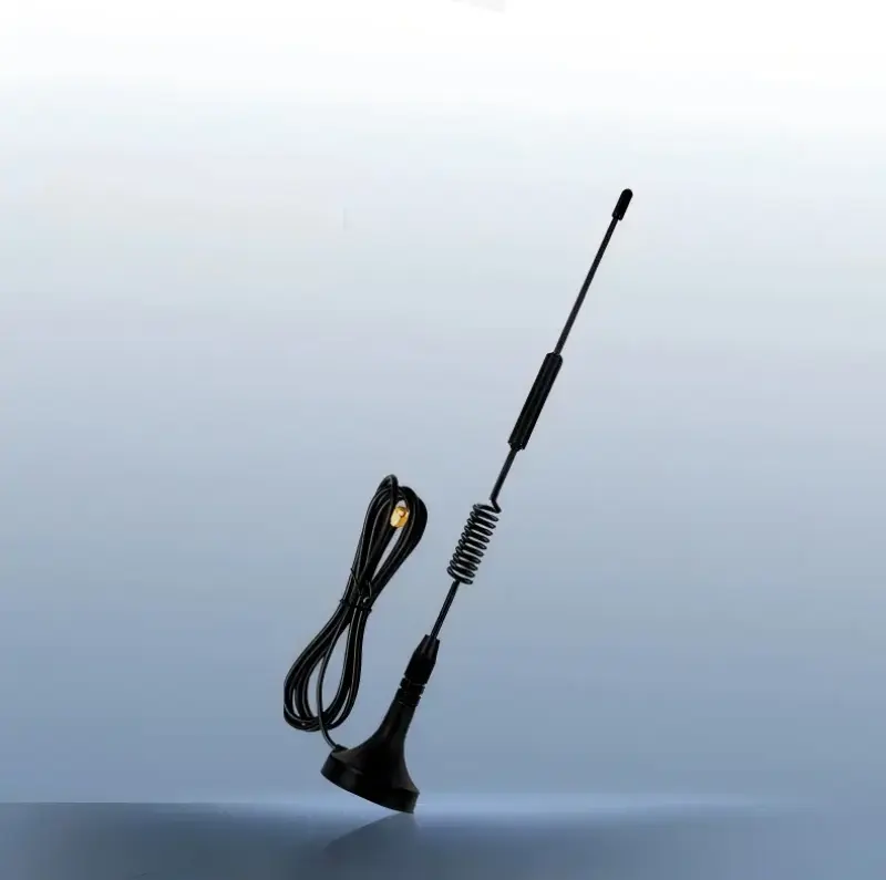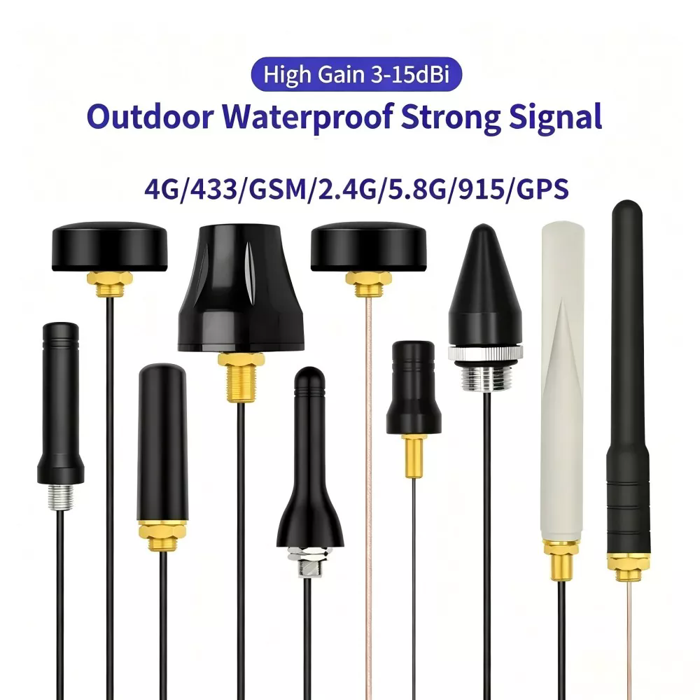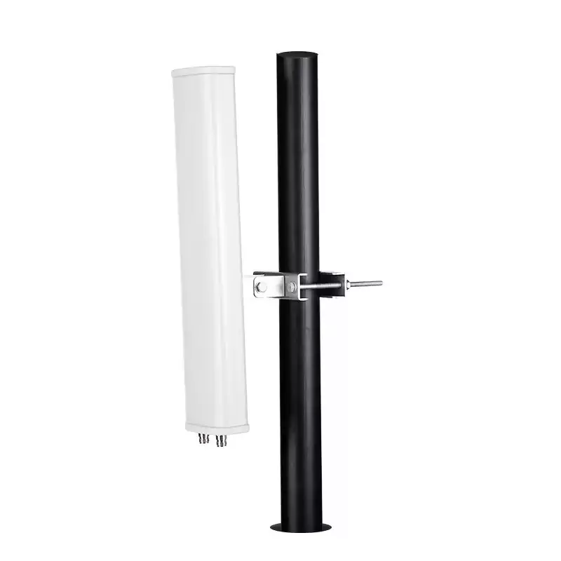
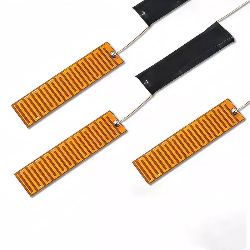
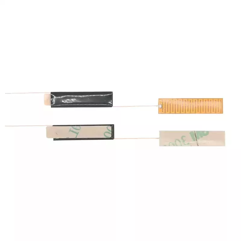
Built-in FM Radio Antenna
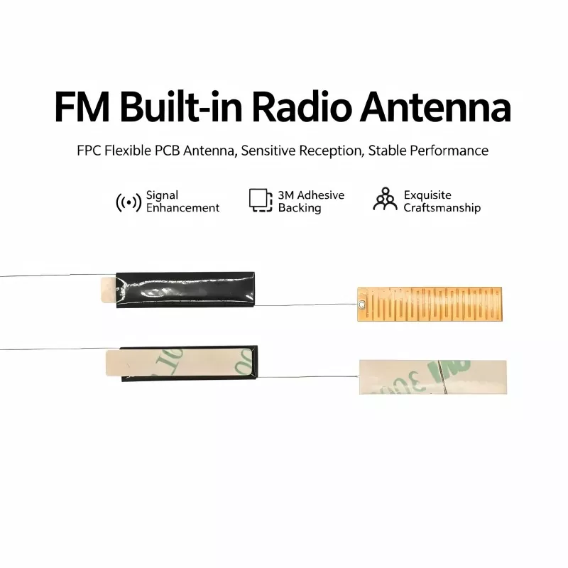
88-108 MHz Built-in FM Radio Antenna designed for car audio systems, Bluetooth speakers, and outdoor portable radios. Manufactured by Shenzhen Qianmu Communication Technology Co., Ltd., a professional China antenna manufacturer offering OEM and ODM customization.
Built-in FM Radio Antenna is a compact RF receiving component designed for 88–108 MHz FM broadcast applications. With a ferrite core and precision coil winding structure, it delivers reliable signal reception performance for car audio systems, Bluetooth speakers, portable radios, and other FM-enabled electronic devices.
What Is the Built-in FM Radio Antenna?
A built-in FM radio antenna is an internal passive antenna module integrated into electronic devices to receive FM broadcast signals. It is mainly composed of a high-permeability ferrite core, precision-wound enameled copper wire, insulation protection layer, and connection terminals.
Compared with conventional external telescopic antennas, this antenna adopts a magnetic induction design that uses the ferrite core to concentrate high-frequency magnetic fields and improve signal reception efficiency. Its compact structure allows manufacturers to integrate FM reception capability into space-limited devices while maintaining a clean product appearance.
Working Principle
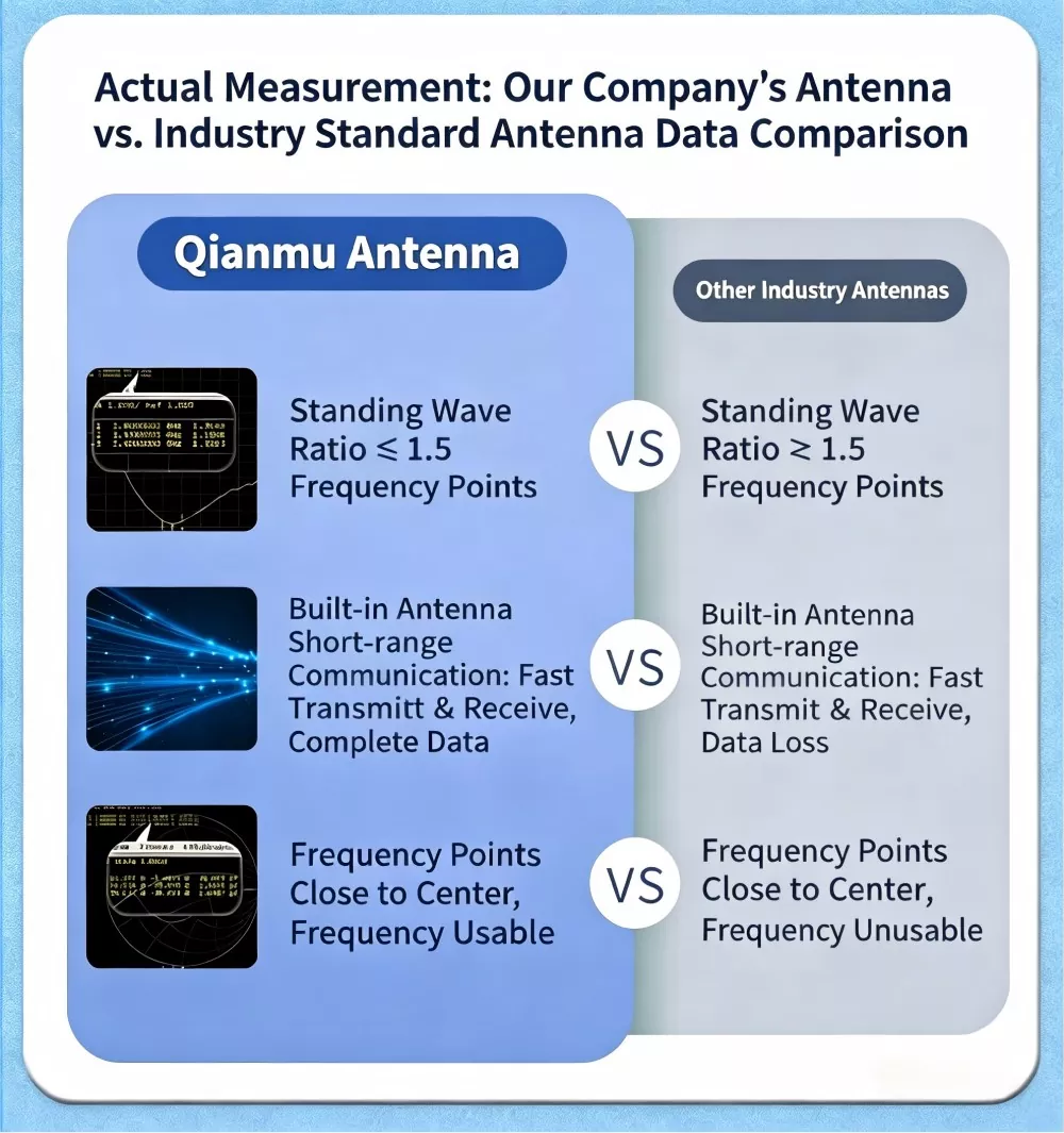
The working principle of the built-in FM radio antenna is based on electromagnetic induction and magnetic field resonance. Its performance can be verified through practical testing with professional equipment such as spectrum analyzers and signal testers.
1. Magnetic Field Concentration
The high-permeability ferrite core is designed to concentrate high-frequency magnetic fields efficiently, enabling the antenna to capture FM electromagnetic signals within the 88–108 MHz frequency range. This structure improves weak signal reception capability and helps reduce signal attenuation caused by long-distance transmission compared with conventional antennas.
2. Electromagnetic Conversion
The precision-wound enameled wire coil around the ferrite core converts the captured high-frequency magnetic field signals into electrical signals. This process enables efficient conversion from electromagnetic waves into radio frequency signals for further processing.
3. Frequency Resonance
By optimizing the coil winding turns and spacing, the antenna is precisely tuned to match the standard FM frequency band. The resonance design helps filter unwanted interference, improve signal stability, and maintain clear audio quality during radio reception.
4. Signal Transmission
The converted electrical signal is transmitted through dedicated pins or connecting cables to the FM decoding circuit of the device. After signal amplification and decoding, it is converted into clear audio output, ensuring stable and reliable FM radio performance.
Compatible Devices
Our built-in FM radio antenna is compatible with the vast majority of electronic devices on the market that feature FM radio functionality. It supports a full range of consumer, commercial, and industrial-grade devices. Specific compatible devices are as follows:
• In-vehicle electronic devices: In-car MP3 players, in-car audio/video heads units, in-car Bluetooth radios, and bus public address systems
• Smart Home Devices: Smart speakers, Bluetooth speakers, wall-mounted home audio systems, background music systems
• Portable Digital Devices: Portable radios, card-slot speakers, vintage radio equipment, portable outdoor audio-visual terminals
• Industrial communication equipment: Industrial FM receivers, outdoor broadcast base stations, security intercom and radio equipment
• Small Appliance Accessories: FM radio alarm clocks, waterproof bathroom speakers, smart kitchen audio-visual appliances

Core Advantages
High Magnetic Permeability & Enhanced Signal Reception
Using high-density ferrite cores with stable magnetic permeability and low high-frequency loss, the antenna improves FM signal sensitivity and reception stability. Combined with precision winding technology, it provides reliable performance under weak signal conditions while reducing audio distortion and signal interruption.
Precise Winding for Stable Frequency Performance
Produced with automatic winding equipment, the coil turn tolerance is controlled within ±1 turn. The antenna is accurately tuned to the global 88–108 MHz FM band, ensuring stable resonance and consistent frequency performance.
Compact Design for Easy Integration
The miniature and ultra-thin structure allows easy installation inside compact electronic devices without external antennas or additional mounting space, making it suitable for space-limited applications.
Anti-Interference Design for Clear Audio
With enhanced insulation layers and shielding structures, the antenna helps reduce electromagnetic interference from circuit boards, chips, and power components, improving signal purity and audio clarity.
Wide Temperature Range & Long Service Life
Made with heat-resistant enameled wire and flame-retardant insulating materials, the antenna operates reliably from -20℃ to +70℃. It is suitable for automotive, outdoor, and indoor applications with long-term stable performance.
Flexible Customization for Different Devices
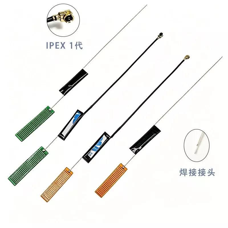
Customized options include ferrite core size, coil winding parameters, lead length, pin materials, and connector types. The antenna can be adapted to different PCB layouts and device structures, with samples available for testing.
Technical Specifications
|
Parameter Item |
Standard Specifications |
Parameter Description |
|
Operating Frequency Band |
88–108 MHz |
Global FM radio frequency band |
|
Antenna Impedance |
50 Ω |
Compatible with mainstream FM receiver board impedance standards |
|
VSWR |
≤1.8 |
Extremely low signal loss and high transmission efficiency |
|
Magnetic Core Material |
High-permeability ferrite |
Low high-frequency loss, excellent magnetic concentration |
|
Wire Material |
High-temperature-resistant pure copper enameled wire |
Excellent electrical conductivity, oxidation resistance, and high tensile strength |
|
Operating Temperature |
-20°C to +85°C |
Suitable for a wide range of high- and low-temperature environments |
|
Storage Temperature |
-30°C to +75°C |
No performance degradation during storage and transportation |
Competitive Advantages Over Peer Products
Currently, the mainstream FM reception antennas on the market are divided into three categories: PCB antennas, external telescoping antennas, and standard coiled antennas. Our built-in FM radio antenna significantly outperforms comparable products from competitors in terms of overall performance, offering outstanding value for money and practicality:
|
Comparison Criteria |
Standard PCB FM Antenna |
External Telescopic FM Antenna |
Our Built-in FM Radio Antenna |
|
Reception Sensitivity |
Low; weak signals are prone to dropouts |
Moderate; highly affected by angle |
High; stable reception of weak signals |
|
Interference Resistance |
Poor; susceptible to circuit interference |
Moderate; susceptible to environmental interference |
Strong; dual-layer insulation provides protection against electromagnetic interference |
|
Installation Flexibility |
Fixed design, cannot be customized |
Protrudes externally, affecting appearance |
Fully customizable parameters; built-in, concealed installation |
|
Service Life |
Prone to oxidation; performance degrades within 1–2 years |
Prone to loosening and breaking |
Stable with no degradation for over 5 years |
|
Value for money |
Low cost, low performance |
High cost, complex structure |
Direct from the factory, offering great value and high performance |
Illustrated Installation and User Guide
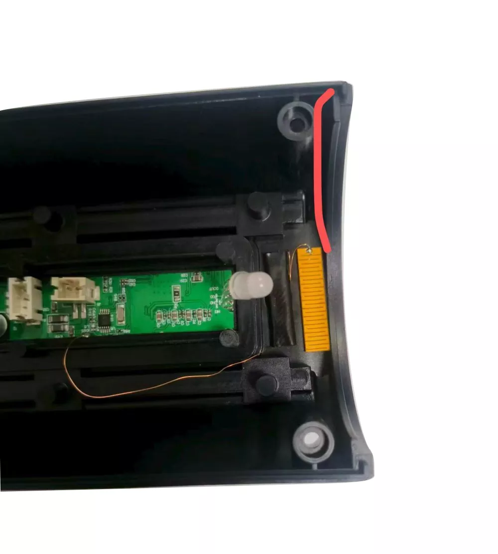
The built-in FM radio antenna is designed for easy installation and can be integrated into various electronic devices. The standard installation steps are as follows:
Step 1: Positioning
Place the FM magnetic coil antenna on a flat and unobstructed area inside the device, keeping it away from motherboard chips, power components, and heat sources to reduce electromagnetic interference and thermal impact. For better reception performance, install the antenna close to the inner surface of the device housing.
Step 2: Fixing the Antenna
The antenna is equipped with an insulated adhesive backing. Remove the protective film and attach it directly to the installation surface. For devices with metal internal structures, the ferrite core can help secure the antenna position without additional adhesive, allowing easy installation and removal.
Step 3: Wiring and Connection
Connect the antenna lead wires or pins to the designated FM antenna connection points on the device PCB by soldering or plugging. Ensure proper contact and avoid issues such as poor soldering, loose connections, or short circuits.
Step 4: Power-On Testing
After installation, power on the device and switch to FM radio mode. Run an automatic station scan to check reception performance. If local FM stations can be received clearly without noticeable noise or interference, the installation is complete.
Product Selection Guide
When selecting a built-in FM radio antenna, price should not be the only consideration. Buyers should evaluate the antenna based on application requirements, compatibility, dimensions, and manufacturing quality. Based on years of industry experience, we provide the following selection guidelines:
1. Choose Based on Application Environment
Standard models are suitable for indoor electronic devices under normal operating conditions. For automotive and outdoor applications, customized models with enhanced temperature resistance, vibration resistance, and signal sensitivity are recommended to ensure reliable performance in demanding environments.
2. Confirm Frequency and Electrical Compatibility
Before purchase, check the device's FM frequency range and circuit requirements. The standard FM band is 88–108 MHz with a typical impedance of 50Ω. Customized frequency tuning is available for special applications.
3. Consider Installation Space and Dimensions
Select the appropriate ferrite core size, coil design, and cable length according to the available installation space inside the device. Compact customized versions are available for applications with limited internal space.
4. Evaluate Material Quality and Manufacturing Process
High-quality antennas typically use pure copper winding wires, high-permeability ferrite cores, and reliable insulation structures. Low-quality antennas may cause unstable reception, signal loss, noise, or electrical failures during operation.
5. Match Procurement Requirements
For small-volume projects, standard samples are available for testing and verification. For bulk orders, customized specifications, packaging, labeling, and OEM manufacturing services can be provided according to customer requirements.
FAQ
Q1: Can the dimensions and wire length of FM magnet-wound antennas be customized?
A: Yes. As a direct manufacturer of built-in FM radio antennas, we support comprehensive customization of core size, number of windings, lead length, connector type, and pin material.
Q2: Compared to standard antennas, does this antenna significantly improve radio reception?
A: Significant performance improvement. Actual tests show signal sensitivity is boosted by over 35% with superior anti-interference capability, effectively resolving channel crosstalk, static noise and signal dropouts caused by building obstructions, electromagnetic interference and weak signals in suburban areas.
Q3: How do you ensure consistency in large-volume production?
A: We use automated winding equipment and a full inspection process, with 100% testing of key magnetic parameters to ensure that the inductance and Q-factor of every antenna fall within the specified tolerance range.
Q4: If a built-in antenna receives fewer stations, is it definitely the antenna's fault?
A: Not necessarily. The number of receivable stations depends on antenna performance, matching circuits, PCB layout, and the sensitivity of the radio chip. Qianmu Communications offers free RF diagnostic services to help you identify the actual cause.
Hot Tags: built-in FM radio antenna, internal FM antenna, FM radio built-in antenna
Send Inquiry
Contact Info
-
Address
Hangcheng High-tech Industrial Park, Hangkong Road, Sanwei Community, Hangcheng Subdistrict, Bao'an District, Shenzhen City, Guangdong Province, China
-
Tel
-
E-mail
Contact Qianmu Communication for professional antenna solutions and customized manufacturing services. As a reliable antenna manufacturer, supplier and factory in China, we provide technical consultation, product customization, sample testing and production support for customers worldwide.