NFC Antenna
Shenzhen Qianmu Communication Technology Co., Ltd. (abbreviated as Qianmu Communication) is a professional manufacturer and supplier of NFC embedded soft antennas and active NFC antennas. We are committed to providing global customers with high-performance, ultra-thin, and metal-interference-resistant near-field communication antenna solutions.
What is an NFC-integrated soft antenna? What is an active antenna?
1.1 NFC Built-in Soft Antenna (FPC Flexible Antenna)
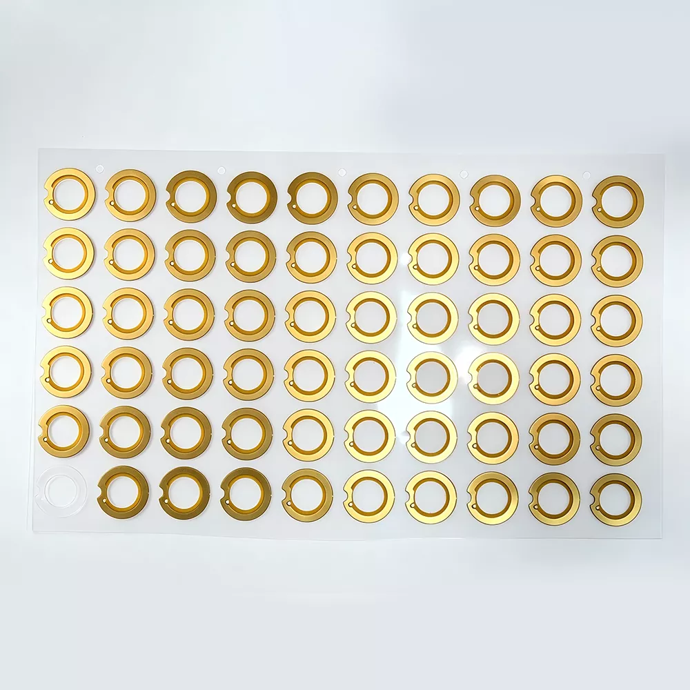
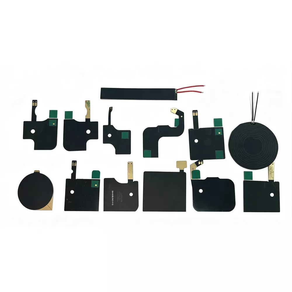
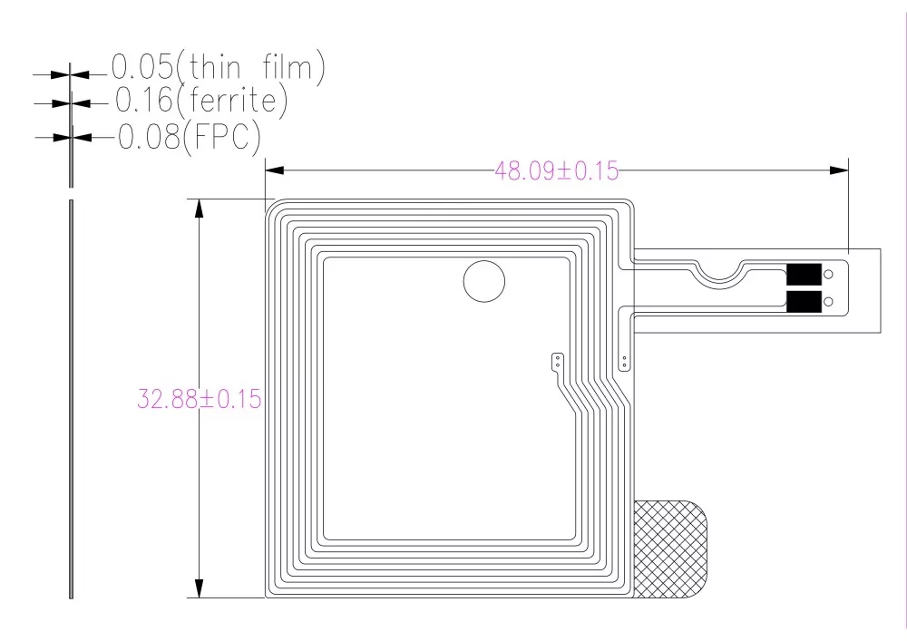
The NFC built-in flexible antenna (NFC Flexible Printed Circuit Antenna) is a type of NFC Antenna manufactured on a flexible printed circuit board (FPC) substrate and designed to operate at the 13.56 MHz frequency band. It uses electrolytic copper as the conductive coil material and adopts a precision etching process to form customized coil patterns with specific turns and geometrical structures. Combined with a ferrite magnetic film as an isolation layer, this flexible antenna can be easily integrated into electronic devices through 3M adhesive or peel-off mounting solutions.
Core components:
- FPC substrate: A flexible circuit board material that provides lightweight and bendable characteristics, with a thickness ranging from 0.14–0.27 mm.
- Copper coil: Manufactured through electrolytic copper etching, the coil structure determines the antenna inductance and resonance frequency performance.
- Ferrite layer: A high-permeability magnetic material that reduces metal interference, improves magnetic field isolation, and enhances signal transmission directionality.
- Adhesive layer: Uses original 3M adhesive materials, offering reliable bonding strength and excellent high-temperature resistance.
- Connection methods: Supports various connection options, including IPEX terminals, soldering heads, spring contacts, and other customized interfaces.
1.2 NFC active antenna
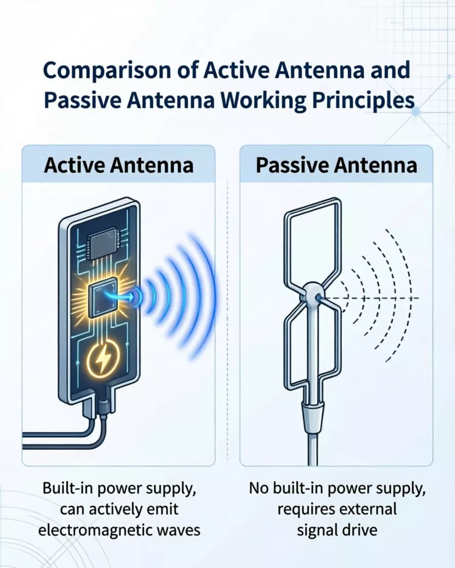
An Active NFC Antenna refers to an antenna system that, based on a conventional NFC antenna, integrates an active contactless frontend or signal amplification/driving circuitry.
|
Comparison dimension |
Passive NFC antenna |
Active NFC antenna |
|
Power supply |
Relies on magnetic field induction from the reader/writer for power supply, eliminating the need for an external power source. |
Features a built-in independent power source (battery-powered / device system-powered) |
|
Signal-driven mode |
Passive response, capable only of receiving and reverse-modulating signals after sensing the reader's magnetic field. |
Actively driven, capable of autonomously generating a stable RF field. |
|
RF output power |
Limited by the reader's magnetic field strength, the output power is fixed and relatively low. |
The built-in amplification circuit allows for active gain adjustment, and the output power can be tailored as needed, with an even higher upper limit. |
|
Effective reading distance |
The standard effective distance is ≤10 cm; after metal obstruction, the distance is significantly reduced. |
Power amplification can significantly extend the read range - 2 to 3 times that of a passive antenna under the same environmental conditions. |
|
Core Typical Applications |
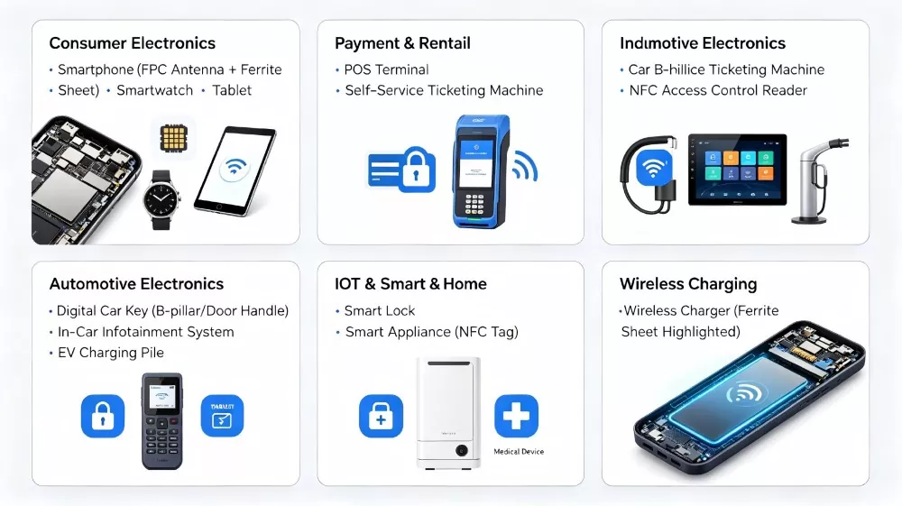
Standard NFC tags, access control IC cards, mobile phone NFC card emulation, low-cost passive identification scenarios |
Handheld payment POS terminals, RFID readers for harsh industrial environments, smart door locks with metal housings, and in-vehicle NFC identification devices. |
Applicable Devices
Why choose Qianmu Communication's NFC antenna?
1. Ultra-thin, flexible design - thickness as low as 0.14–0.27mm, perfectly suited for ultra-thin devices and flexible installation requirements.
2. Ferrite isolation layer - Standard ferrite included, effectively shielding against interference from metallic environments.
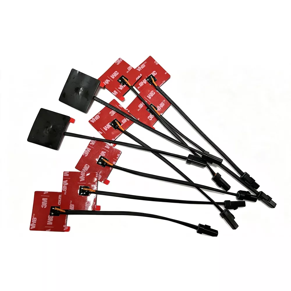
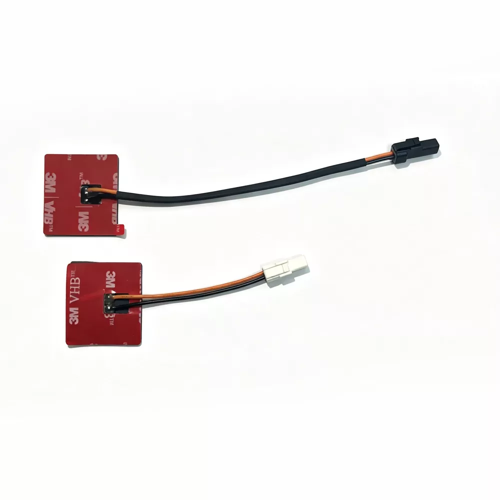
3. Multiple installation methods - supports various options including 3M adhesive backing (removable adhesive), IPEX terminals, and soldering.
4. Wide-temperature operation - Operating temperature range: -40℃ to +85℃
5. Fully compliant with standards - meets RoHS environmental standards
6. Customized Services - Fully customizable support for dimensions, shapes, coil turns, inductance values, and more.
7. Fast Delivery - Rapid sample production and efficient mass production delivery.
8. Professional simulation support - Providing electromagnetic simulations and whole-machine optimization recommendations.
RF Behavior and System-Level Considerations
The performance of an NFC Antenna depends not only on its basic electrical specifications but also on the overall electromagnetic environment created by the final device structure. Factors such as material selection, internal layout, and surrounding components can significantly affect antenna efficiency and communication stability.
1. Metal detuning effect
When an antenna is installed close to metallic components, including batteries, shielding covers, or mechanical frames, the induced eddy currents can alter the electromagnetic characteristics and shift the resonant frequency. Without proper ferrite isolation, this detuning effect may cause resonance deviation, lower coupling performance, and reduced communication reliability.
2. Ferrite layer function in field stabilization
The ferrite magnetic layer provides more than interference protection. It also works as a magnetic flux guidance layer by directing the magnetic field toward the non-metal side of the antenna. This helps improve coupling efficiency, optimize signal transmission, and minimize energy loss in applications where metal components are nearby.
3. Impedance matching sensitivity
NFC systems operating at 13.56 MHz require precise impedance matching due to their sensitivity to changes in enclosure design, adhesive thickness, and coil deformation. Small variations in mechanical structure may influence the resonance point and Q-factor performance, making system-level tuning necessary after antenna integration.
4. Coupling with device architecture
The antenna performance is also affected by the dielectric characteristics of surrounding materials, including plastic housings, glass covers, and PCB stack-up structures. Materials with higher dielectric constants may introduce additional parasitic capacitance, resulting in narrower bandwidth and reduced communication margin.
5. Active vs passive system impact
For active NFC antenna configurations, the driving circuit directly influences the distribution and strength of the electromagnetic field. Although this approach can extend communication distance, it also increases sensitivity to load changes and requires more precise control of grounding, shielding, and overall system design.
Technical specifications
|
Active NFC Flexible Board with Ferrite Antenna - Product Parameter Sheet |
|
|
Parameter |
Specifications |
|
Operating frequency |
13.56MHz ±7kHz |
|
Antenna gain |
2-3dBi |
|
Voltage Standing Wave Ratio (VSWR) |
≤1.5 - ≤2.0 |
|
Impedance |
50Omega |
|
Power |
2-10W |
|
Polarization mode |
Vertical polarization |
|
Antenna Type |
FPC flexible coil + ferrite magnetic film |
|
Thickness |
0.14mm - 0.27mm |
|
Operating temperature |
-40℃ ~ +85℃ |
|
Installation method |
3M-back adhesive mounting / IPEX connector / Soldering |
|
Environmental certification |
RoHS compliant |
Compared with peers: Qianmu Communications' differentiating advantages
|
Comparison dimension |
Thousand-Eye Communication |
Other home antennas |
|
Minimum thickness |
0.20mm |
0.25mm |
|
Ferrite standard configuration |
✅ Standard equipment |
Optional |
|
Adhesive type |
3M original factory glue |
Common domestically produced glue |
|
Standing wave ratio |
≤1.5 |
≤2.0 |
|
Sample delivery time |
10sky |
15sky |
|
RoHS |
✅ Full series |
Some models |
|
Active solution |
✅ Supported |
Not supported |
|
We adhere to a manufacturer-direct sales model, eliminating any intermediary markups. All production stages are carried out in our own factory, ensuring full quality control throughout the entire process. As a supplier deeply rooted in China, we have provided supporting services to numerous well-known brands. |
||
Installation Guide
Adhesive-backed installation (FPC flexible antenna)
This is the most commonly used NFC antenna installation method:
Installation steps:
1. Clean the surface - Use an alcohol wipe to clean the installation area (the inner surface of the device casing or the battery surface), ensuring it is free of oil and dust.
2. Peel off the release liner - carefully remove the 3M adhesive protective film from the back of the antenna.
3. Alignment and Positioning - Align the antenna with the designated installation location, ensuring that the coil area is unobstructed.
4. Press firmly and evenly - from the center toward the edges to eliminate air bubbles.
5. Curing and Waiting - Allow to stand for 24 hours to achieve optimal bonding strength.
Installation Notes:
|
Notes |
Description |
|
Metal Environment Isolation |
When metallic components are present near the antenna, a ferrite layer should be used for electromagnetic isolation. |
|
Bending Limitation |
FPC antennas can be bent but should not be folded; recommended minimum bending radius is greater than 5 mm. |
|
Electrostatic Protection |
An antistatic wrist strap should be used during handling and assembly. |
|
Thermal Control |
Temperature and exposure time must be controlled during soldering to prevent thermal damage. |
Customer reviews
"The NFC built-in soft antenna from Qianmu Communications has demonstrated stable performance in our new smartphone model, achieving a read range of 85mm. The ferrite layer effectively shields against battery interference, and the quality consistency across mass production is excellent." - Brand Manufacturer, Shenzhen Junge Technology Co., Ltd.
"The active NFC antennas used in POS terminals demand high reliability and strong RF fields. Qianmu Communication's products have passed our rigorous EMVCo testing and we've already purchased over 300,000 units." – Guangzhou ZhonghaidaSatellite Navigation Technology Co., Ltd.Payment terminal manufacturer
FAQ
Q1: What is the operating frequency of the built-in soft antenna in the NFC?
A: NFC operates in the internationally standardized 13.56 MHz ±7 kHz frequency band, which is commonly used in near-field communication systems for short-range wireless data transfer.
Q2: What is the typical reading distance?
A: The communication range is generally limited to a few centimeters, typically around 5–8 cm, depending on antenna design, device structure, and installation conditions.
Q3: When is an NFC antenna with a ferrite core required?
A: When the antenna needs to be installed on the surface of a battery, near a metal enclosure, or in an environment with metallic components, it is essential to use an antenna equipped with a ferrite layer. The ferrite layer can effectively isolate reverse eddy-current interference caused by metal.
Q4: What's the difference between an NFC built-in soft antenna and an active antenna?
A: The built-in passive antenna is a passive component that relies on the magnetic field induction from the reader/writer to operate, making it suitable for standard NFC applications. The active antenna integrates signal amplification and driving circuits, enabling it to actively generate a stronger RF field, making it ideal for scenarios such as payment terminals that require a more robust signal.
Q5: Can it be customized in size and shape?
A: Yes, Qianmu Communications supports custom designs in all sizes, including rectangular, circular, and irregular shapes.
Q6: What inductance range is commonly used?
A: Typical designs fall within an inductance range of approximately 1–2 μH, depending on tuning and impedance matching requirements.
Q7: What are common installation methods?
A: There are three main installation methods: ① 3M adhesive backing (FPC flexible antenna - most commonly used); ② IPEX connector (plug-in type); ③ Soldering installation.
Q8: Is Qianmu Communication a trader or a factory?
A: Qianmu Communications is a manufacturer that integrates R&D, production, and sales. We own our own factory and have a complete production line as well as a robust quality control system - far from being merely a trading company.
Hot Tags: NFC Antenna Manufacturer, Supplier, Wholesale
Send Inquiry
Contact Info
-
Address
Hangcheng High-tech Industrial Park, Hangkong Road, Sanwei Community, Hangcheng Subdistrict, Bao'an District, Shenzhen City, Guangdong Province, China
-
Tel
-
E-mail
Contact Qianmu Communication for professional antenna solutions and customized manufacturing services. As a reliable antenna manufacturer, supplier and factory in China, we provide technical consultation, product customization, sample testing and production support for customers worldwide.