How Can a Built-in FM Radio Antenna Improve Signal Reception in Compact Electronic Devices
Qianmu develops the Built-in FM Radio Antenna for compact FM-enabled products that require reliable reception without adding an exposed external antenna. Designed for the 88–108 MHz FM broadcast band, this compact RF component combines a ferrite core, precision-wound copper coil, and flexible connection options for automotive audio systems, Bluetooth speakers, portable radios, smart home equipment, and other electronic devices.
A built-in FM antenna is more than a space-saving replacement for a telescopic antenna. Its ferrite-core magnetic induction structure, precision coil winding, compact form factor, and customizable connection design allow manufacturers to integrate FM reception into products where installation space and appearance are important. This guide explains how a built-in FM radio antenna works, its technical characteristics, suitable applications, installation considerations, and the key factors buyers should evaluate when sourcing an antenna for OEM or ODM projects.
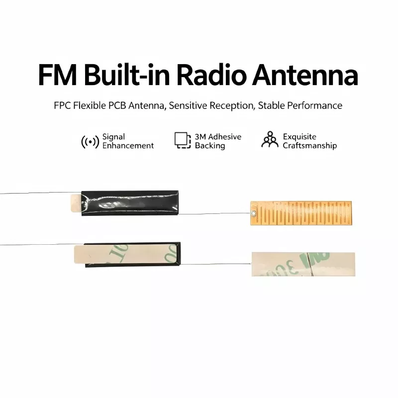
Table of Contents
- What Is a Built-in FM Radio Antenna?
- How Does a Built-in FM Radio Antenna Work?
- What Are the Key Features?
- Where Can It Be Used?
- What Are the Technical Specifications?
- How Should the Antenna Be Installed?
- How Should Buyers Select the Right Antenna?
- How Does It Compare With Other FM Antennas?
- Frequently Asked Questions
- Why Consider a Customized FM Antenna?
What Is a Built-in FM Radio Antenna?
A Built-in FM Radio Antenna is an internal passive RF receiving component designed to receive FM broadcast signals while remaining inside the electronic device. Unlike a conventional telescopic antenna that extends outside the enclosure, an internal antenna can be concealed within the product structure, helping manufacturers maintain a clean appearance while making efficient use of limited internal space.
A typical ferrite-core design consists of a high-permeability ferrite core, precision-wound enameled copper wire, insulation protection, and connection terminals or lead wires. The ferrite material concentrates the magnetic field around the coil, while the winding structure is engineered to support reception across the intended FM frequency range.
For manufacturers developing compact consumer electronics, this structure can simplify product integration. The antenna can be positioned according to the PCB layout and enclosure design rather than requiring a dedicated external antenna opening.
For more product-specific information, buyers can review the Built-in FM Radio Antenna product page.
How Does a Built-in FM Radio Antenna Work?
The operating principle is based primarily on electromagnetic induction and resonance. When an FM broadcast signal reaches the antenna, the ferrite core helps concentrate the high-frequency magnetic field around the coil. The precision-wound conductor then converts the electromagnetic energy into an electrical RF signal that can be processed by the receiving circuit.
1. Magnetic Field Concentration
The high-permeability ferrite core concentrates high-frequency magnetic fields around the winding. This structure is particularly useful when manufacturers need an antenna that can fit into a compact internal space while maintaining dependable FM reception.
2. Electromagnetic Conversion
The copper coil surrounding the ferrite core responds to the changing magnetic field and generates an electrical signal. This signal is then transferred through the antenna connection to the FM receiver circuit.
3. Frequency Resonance
Coil winding parameters, including the number of turns and winding arrangement, influence the antenna's frequency characteristics. Proper tuning helps the antenna operate within the intended FM band and supports stable reception.
4. Signal Transmission
After conversion, the received RF signal travels through the antenna lead or connection pins to the FM receiver circuitry, where it is amplified, decoded, and converted into audio output.
What Are the Key Features?
When selecting an internal FM antenna for a commercial product, engineers typically consider reception performance, physical dimensions, interference resistance, operating temperature, and integration flexibility. The following characteristics make a ferrite-core built-in design suitable for many compact devices.
- 88–108 MHz operating range: Designed around the commonly used FM broadcast frequency range.
- Compact internal structure: Allows manufacturers to integrate FM reception without a protruding external antenna.
- Precision coil winding: Supports consistent electrical characteristics and frequency performance.
- Ferrite-core construction: Concentrates magnetic fields and supports efficient signal reception.
- Interference-conscious design: Insulation and structural considerations can help reduce unwanted electromagnetic interference.
- Flexible customization: Core dimensions, winding parameters, cable length, pins, and connectors can be adapted to product requirements.
- Wide operating temperature: The referenced Qianmu design specifies operation from -20°C to +85°C.
Where Can It Be Used?
The compact structure of an internal FM antenna makes it suitable for products where external antenna exposure is undesirable or impractical. Applications can range from consumer electronics to automotive and industrial equipment.
| Application | Typical Device | Primary Integration Requirement |
|---|---|---|
| Automotive Audio | Car audio systems, Bluetooth radios, multimedia head units | Compact installation and stable reception |
| Portable Electronics | Portable FM radios and outdoor audio devices | Small size and reliable signal reception |
| Smart Home Audio | Smart speakers and wall-mounted audio systems | Concealed antenna integration |
| Small Appliances | FM alarm clocks and bathroom speakers | Space-efficient internal installation |
| Industrial Equipment | FM receivers and communication equipment | Stable RF performance and application-specific customization |
What Are the Technical Specifications?
Technical specifications should always be matched to the receiver circuit, enclosure, installation position, and target market. The following specifications represent the referenced Qianmu product configuration and can serve as a starting point for engineering evaluation.
| Parameter | Specification | Engineering Consideration |
|---|---|---|
| Operating Frequency | 88–108 MHz | FM broadcast reception |
| Antenna Impedance | 50 Ω | Designed for mainstream FM receiver interfaces |
| VSWR | ≤1.8 | Supports efficient RF signal transfer |
| Magnetic Core | High-permeability ferrite | High-frequency magnetic concentration |
| Wire Material | Pure copper enameled wire | Electrical conductivity and durability |
| Operating Temperature | -20°C to +85°C | Suitable for varied application environments |
| Storage Temperature | -30°C to +75°C | Supports transportation and storage requirements |
Actual performance can vary according to the receiver IC, PCB layout, enclosure material, surrounding electromagnetic environment, local signal strength, and antenna installation position. Therefore, prototype testing remains important before mass production.
How Should the Antenna Be Installed?
Correct placement is essential for achieving consistent FM reception. Even a well-designed antenna can experience reduced performance if it is positioned close to strong interference sources or unsuitable materials.
Step 1: Select the Installation Position
Place the antenna in a relatively open internal area and, where practical, close to the inner surface of the enclosure. Avoid placing it directly beside high-frequency chips, power components, heat sources, or other strong interference sources.
Step 2: Secure the Antenna
An insulated adhesive backing can provide a simple installation method for compatible designs. The mounting method should keep the antenna firmly positioned and prevent movement that could affect repeatability during product operation.
Step 3: Connect the Antenna
Connect the antenna lead or pins to the designated FM antenna interface on the PCB. Soldered connections should be secure and free from shorts, while plug-type connections should have sufficient mechanical retention.
Step 4: Test Reception
After assembly, power on the device and perform an FM station scan. Evaluate station count, audio clarity, background noise, signal stability, and reception consistency at different locations.
How Should Buyers Select the Right Antenna?
Price alone should not determine antenna selection. For OEM and ODM projects, purchasing teams and engineers should evaluate the antenna as part of the complete RF system.
- Confirm the frequency range: Ensure the antenna is suitable for the target FM broadcasting band.
- Check the available space: Provide accurate enclosure and PCB dimensions before selecting the antenna structure.
- Review the connection method: Specify cable length, terminal design, connector type, or PCB connection requirements.
- Evaluate the operating environment: Automotive, portable, indoor, and outdoor products may require different mechanical and thermal considerations.
- Consider electromagnetic interference: Identify nearby processors, switching power supplies, displays, motors, and other potential noise sources.
- Request samples: Test the antenna in the actual enclosure and with the intended FM receiver circuit before approving mass production.
- Discuss customization: For volume projects, customized core dimensions and winding parameters can provide better integration than a generic antenna.
How Does It Compare With Other FM Antennas?
Different antenna structures serve different product requirements. A PCB antenna may be convenient when the PCB provides sufficient space, while a telescopic antenna can be useful when an exposed antenna is acceptable. A ferrite-core built-in design is particularly relevant when manufacturers prioritize concealed installation and compact mechanical integration.
| Factor | PCB FM Antenna | Telescopic FM Antenna | Built-in Ferrite FM Antenna |
|---|---|---|---|
| Installation | PCB-dependent | External | Internal |
| Product Appearance | Clean | Visible antenna | Concealed |
| Space Requirements | Requires PCB area | Requires external clearance | Suitable for compact internal spaces |
| Customization | PCB redesign may be required | Limited by mechanical structure | Core, winding and cable options can be customized |
| Typical Applications | Compact electronics | Traditional radios | Automotive, portable and smart audio devices |
Frequently Asked Questions
1. What frequency does a Built-in FM Radio Antenna support?
The referenced Qianmu antenna is designed for the 88–108 MHz FM broadcast band. Specific frequency requirements can be discussed during customization for different applications and markets.
2. Can the antenna dimensions and cable length be customized?
Yes. Customization can include ferrite core size, coil winding parameters, lead length, pin materials, and connector types. These options allow the antenna to better match the available enclosure and PCB layout.
3. Is a built-in antenna suitable for automotive audio systems?
Yes. Built-in FM antenna designs can be integrated into in-car audio systems, Bluetooth radios, multimedia head units, and similar equipment. Automotive projects should be evaluated through actual installation and RF testing because vehicle structures and electronics can affect reception.
4. Does antenna performance depend on PCB layout?
Yes. Reception performance is influenced not only by the antenna but also by the receiver IC, PCB layout, grounding, surrounding components, enclosure structure, and electromagnetic environment. Prototype testing is recommended before mass production.
5. Can samples be provided before bulk production?
Sample evaluation is an important part of customized antenna development. Buyers can discuss sample requirements with Qianmu and test the antenna within the intended device before moving to volume production.
Why Consider a Customized FM Antenna?
For manufacturers developing FM-enabled electronic products, the antenna should be selected as an integral part of the RF system rather than treated as a standalone accessory. A well-matched built-in design can help conserve installation space, maintain a clean enclosure appearance, and provide a practical solution for automotive, portable, smart home, and industrial FM applications.
Qianmu provides built-in FM antenna solutions with customization options covering ferrite core dimensions, coil winding, cable length, connection terminals, and structural integration. For OEM and ODM projects, engineering teams can define their frequency requirements, available space, PCB interface, operating environment, and expected reception performance before sample validation. If you are developing a new FM-enabled product or looking for a reliable China antenna manufacturing partner, contact us to discuss your application, request a customized solution, and start sample evaluation with Qianmu.
Related News
- Qianmu Launches Custom LDS 3D Antenna Solutions for Wearable, Automotive & Compact IoT Devices
- How Can the Right NB-IoT Antenna Improve Connectivity and Reliability for Industrial IoT Devices
- How Can the Right DAB Antenna Improve Digital Radio Reception in Modern Vehicles
- FPC vs. PCB Antennas: Key Differences for Compact Electronic Devices
- Shenzhen Qianmu Communication Technology Co., Ltd. Launches High-Performance Smart Water Meter Antenna for Global Smart Water Projects
- Why Is a Built-in FM Radio Antenna a Smart Choice for Modern Audio Devices
Leave me a message